The Disting Mk4 is a high-precision digital utility module packed with multiple functions(algorithms)in a 4HP.The following functions have been added From Mk3 to Mk4
Adding a dot matrix display: added a display that can display characters, such as algorithm names
Micro SD card slot is now accessible from the front
Several algorithms have been added that require a display function, such as a tuner.
It is similar to Mk3 in terms of algorithms and basic operations that do not require a display.The Mk3 will also be updated whenever new algorithms are added in the future.
How to Use
Choosing an algorithm
In the Disting, we use various algorithms to switch.
The algorithm can be easily selected by pressing and turning the S encoder.Or click the S encoder 1 time to enter the menu Mode, Click 1 degree as it is, the algorithm can be switched by the S encoder.
Menu
As mentioned above, in the Disting, you can click the S encoder toMenuIt is possible to get into theThe menu is up to 1 to 4 as follows and can be selected by the rotation of the encoder.Click the S encoder again to determine the selected menu.
Menu 1-switching algorithm
Menu 2-blank (bank selection until Firmware 4.0)
Menu 3-help: For the Disting displayHelp filewhen you copy the "help" folder in the (zip) to the micro SD card, the display displays the help for each algorithm written there
Menu 4-settings: Set the brightness (Briteness), Auto-Store, enable/disable the recall function
Menu 5-calibration(if you select this menu by mistake, click the Z knob to return to the original)
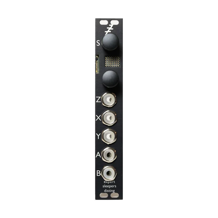
Knobs/Jacks
Then, "X"and"Y"inputs are 2 signal inputs, and"A"and" B " are 2 signal outputs.The X,Y,A, and B DA / AD converters are 24-bit and highly accurate.
The Z-knob is a knob for performing a specific control(Z-control) for each function. The"Z"CV input below it is a jack for performing Z control at a voltage.Also, some algorithms can control a parameter other than the Z control with up to 4 S encoders.If there is more than one controllable parameter, the parameter to be controlled by the S-encoder is switched after each click of the Z-knob(the accuracy of the parameter to be controlled by the encoder is less than that of the other parameters).
The Z-knob movement, except for the algorithm that requires the click of the Z-knob for the above reason.RecordIt is possible to use the following functions:When you hold down the Z knob, the movement is recorded up to nearly 14 seconds, and when you release it, the recorded movement is looped.
In some algorithms, the clock input is changed by clicking the Z knob multiple times.Tap tempoYou can also use it as a reference for your business.However, if you have a clock divide setting of 1/4, please tap 5 times(example).
The selected algorithm and its parameters are also remembered when the power is turned ON/OFF.
Favorites
Up to 16 favorite algorithms can be collected in the algorithm of O1〜P8. In the top folder of the micro SD card, select " favourites.place the text file with the name " txt " and list your favorite algorithm in the following format.
disting favourites v2 B8 VCO a1 C5 resonator I4 SD z speed b5 LFO e6 dual AR w/ push
Please write"rating favourites v2"in line 1 as it is.The following lines will be your favorite algorithm, and the algorithm will be separated by a space for each line.You do not have to write a text such as"VCO"following the algorithm number.
Firmware Update
Firmware update is available using a micro SD card. About the procedureVideo of Expert SleepersPlease see also.
The power of the Disting is turned off
Expert SleepersSiteDownload the latest firmware from (at the bottom of the linked page).
Unzip the Zip file
Image of the unzipped folder.copy the hex file to the folder at the top of the micro SD card.The file name is image.please fix it when it is not hex
Plug the micro SD card into the slot.
Turn on the charging while holding the S knob
"Confirm...Please press the S knob until the letter " s " appears
Release the S knob to start the update.
When the update is finished,"SUCCESS" is displayed, so please wait without turning off the power until then
After the update, turn off the power supply and turn on the power supply again, and the new firmware will be available normally.
List of Algorithms
The algorithm that is currently installed(2017 8 months, firmware version 4.3)is as follows.No more bank concept than firmware 4.1, the algorithm will be listed as A1, A2,---A8, B1, B2 ...
For the latest list of features, see the Expert SleepersProduct pageSee .
1
2
3
4
5
6
7
8
a
Precision, Asda.
Ring modulator
Full-wave Rectifier
Max / min
Lin / Exp conversion
Quantum Tizer
Comparator
Dual-wave shaper
b
Sample & amp;hold
Through-the-limiter
Pitch envelope detection
Clock-sinking delay
LFO
Clock-sinking LFO
Linear FM VCO
VCO with wave shave
c
Precision adder(offset difference)
Voltage controlled delay line
Clock syncable ping-pong delay (Z: feedback)
Clock syncable PingPong delay (Z: pan)
Resonator.
Voscorder
Phaser
Bit crusher
d
Uh ...
Tape delay
Wave form animator
State variable filter
LP / HP filter
LP / BP filter
BP / HP filter
BP / Notch filter
e
AR envelope
AR envelope (with push)
AR ENV & VCA
AR ENV & VCA (with push)
Dual AR envelope
Dual AR envelope (push)
Eurorac→bookla conversion
Bookla→eurolac conversion
f
Clock-assisted AD envelope(mute)
Clock-assisted AD envelope(gate)
Clock-assisted AD envelope(trigger)
With clock AD ENV & amp; VCA
Shift register random CV
Shift register random CV(quantize)
Shift register random trigger
Shift register random dual trigger
g
ES-1 emulation
ES-2 emulation
Pitch reference
Frequency reference
The tuner
MIDI clock
MIDI/CV
CV/MIDI
h
Crossfade / bread
Dual sample & amp;hold
Dual quantum Tizer (Z: scale)
Dual quantum Tizer
Dual Euclidean sequencer
Dual delay pulse generator
Noise
Uh ...
I
Audio playback
Audio playback(With clock)
Audio playback(1V / Oct)
Audio playback (Z: playback speed)
Uh ...
Uh ...
Uh ...
Uh ...
J
MIDI file playback (with clock)
Uh ...
MIDI file playback
Audio playback(end CV)
Audio recording
Uh ...
Uh ...
Uh ...
K
Web table VCO
Uh ...
Uh ...
Uh ...
Uh ...
Uh ...
Uh ...
Uh ...
L
Stereo reverb
Mono In stereo reverb
Dual reverb
Uh ...
Stereo chorus
Mono chorus
Uh ...
Uh ...
The description of each algorithm is given below.(Some algorithmic comments will be forthcoming)
A-1:Precision adders A outputs a voltage signal of X+Y and b outputs a voltage signal of X-Y.The Z control also increases the output of A and B in 1V increments.
A-2: Ring Modulator It is also VCA which becomes a ring modulator.Since the input signals of X and Y are multiplied, X can be used as VCA if the audio and Y envelopes are included,and Y can be used as a ring modulator if the audio signal is also input.Output b outputs a signal that inverts A vertically.
Also, the Z control is a control that increases the output signal size to an integer multiple or divides it by an integer multiple(1 / 10x to 10x).
A-3 Full-wave Rectifier Take the lower half of the waveform(0 or more)and wrap it up.Works like a wave folder.The Z knob switches between 2 modes, and the"independent" mode wraps around 2 inputs, each outputting from 2 outputs.in "combined" Mode, a signal Plus X and Y and a signal minus Y from X is processed and output from a/B.
A-4:Max / Min From the output of A and B, We output the larger and smaller of the 2 input signals, respectively. (In the majority of the video below, 1 input has a constant voltage)
A-5: Lin / Exp conversion This converter can convert 1V / Oct pitch to Hz / V pitch signal.You will be able to control the analog pitch of Korg and Yamaha with the eurolac sequencer."Hz/V" is a common term, and among the synths of this type, Yamaha'S CS-15 is 1100Hz/V, with frequencies that rise at 1V depending on the model.Adjust the scale with the Z-knob.(1100Hz / V is roughly around the middle of the Z-knob)
A-6: quantum Tizer This is a quantizer that outputs the X input from A along the voltage signal of the scale.B outputs a trigger signal only when the output signal of A changes.The Y input can be selected 2 ways by the Z knob, and the Y input is transposed when Z is+, and the signal with the quantized quantile of input voltage is added is output from A.When Z is -, it becomes the trigger mode, and the signal from A changes to the voltage quantized at that time, only at the moment when Y input receives the trigger.The time when the trigger is not received will keep that signal.Features like sample & amp;hold.
You can change the scale by the Z-knob.The scale is displayed in the way of lighting of the LED a ~ D.
A-7 comparators: When the signal to X is greater than the signal to Y, A 5V gate signal is output from A.B is the opposite of A, and the gate signal is output when Y is greater.
A-8 : dual wave shapers: 2 Wave shapers.Input X passes through the so-called Wave folder, and the overtone is added to output from A.The way of folding also changes depending on the gain.Input Y is a special wave shaper called Triangle→sine wave, which can be used to add subtle warmth to the sound or to create a pure sine wave from a triangle wave.
B-1 : sample & amp;hold From A, it outputs the signal of the X Input sampled at the moment the Y input is triggered and keeps it until the next trigger enters the Y input.Since white noise is output from B, if you want to output random sample&Hold, please self-patch from B to X.The Z controls the sample & amp;held signal as a slew limiter.
B-2 :slew limiter A and B output signals that add X and Y through a slew limiter.B is better for the characteristics of the change is smooth.Z determines the speed of the thru.
B-3: Pitch & amp; envelope detection Detects the pitch and envelope of the signal to X input, and outputs it from a/B.If the pitch detection fails, the envelope is not output from B.Y input is the input to add voltage to the output pitch CV.Z changes the accuracy of the pitch detection as well as the accuracy of the envelope detection as a trade-off.
B-4 :clock syncable delay / echo The clock interval input to the Y input is set to the delay time, and the audio signal to The X input is set to the delay output from A/B.Only dry / wet mixed signals are output from A and wet signals from B.The Z-knob / Jack also controls the feedback and the mix balance of signals from A.If the delay time is more than about 750ms, the delay time will be 1/2 so that it is less.
B-5 :LFO It outputs SAW/SINE/TRIANGLE from A, and pulse wave from B. Both the X and Z inputs control the speed of the LFO.Y input changes the waveform or pulse width of the output LFO.
B-6 :clock-synchronized LFO Outputs an LFO from A/B that is synchronized to the clock input to the X Input.The output waveform and the point at which the waveform is controlled by Y are the same as the LFO in 4-A.The big difference is the Z control, which allows you to control how many times the LFO is clocked and how many times it is clocked.(Clock divider / multiplier)
B-7: FM VCO Linear FM (TZFMMM)can work as VCO.The pitch CV input, where X is 1V / Oct,and Y is FM input.The Z control allows you to adjust the tuning with a width of 1 octave.Each output produces a sine wave and a sawtooth wave.
B-8 :VCO with waveshapes A VCO that outputs signals of different waveforms from A and B.The waveform and Y input controls are the same as the LFO.The X input is the pitch CV input of 1V/Oct.The Z controls tuning at 1 octave.
C-1: Precision adders (offset difference) It is the same precision as the preset 1/a in bank 1, but the offset is a constant voltage of 1 / 12V(equivalent to semitone
C-2: voltage controllable delay line The maximum delay time is 200 milliseconds.Y becomes the CV input for the delay time, and Z controls feedback.A output is the output of only the delay sound, B output is the output of 50/50 mixed with the original sound.
C-3: clock ping pong delay(Z = feedback) It will be a clock syncable ping-pong delay.Y is the clock input, Z is the feedback, and a/B is the left・right output.
C-4: clock delay (Z = input pan) This is a clock-synchronous ping-pong delay that allows you to pan the input.Y is the clock input, Z is the input pan, and A/B is the left・right output.
C-5: resonator The resonator is a strong kind of resonance filter.It can also be used to generate drum sounds using oscillation.In that case, input the trigger instead of the sound to The X Input.Y is 1V/Oct at the resonator's pitch input.0V is mostly C3 (about 130.81 Hz).The Z is the gain and, in the case of drum sound generation, the decay time is controlled.A outputs the resonator, and B outputs the sound envelope.
C-6: vocoder This is the vocoder where X is the modulator input and Y is the carrier input.Z sets the decay time of the envelope follower in the vocoder.A is the audio output and B is the envelope output.
C-7: phaser X is the audio input,Y is the sweep.Z controls feedback.When Z is negative, the feedback also becomes negative feedback, producing a different sound.A is the mix of phaser sound and original sound, and B is the output of phaser sound only.Parameter 1, controlled by the S knob, sets the number of stages of the Phase Shift.
C-8: Bit Crusher X sets signal input, Y is sample rate input, Z sets bit reduction. A is the signal output and B is the comparator output.
D-2: Tape Delay This is a delay that simulates a tape echo. X is the audio input, And Y is the tape speed. Control feedback with Z. A is the mix of the delay sound and the original sound, and B becomes the output only of the delay sound.
D-3: Wave Form Animator
D-4: State Barrier Filter A state barrier filter that changes with low pass, band pass, and high pass by Z. Controls the cutoff with Y.
D-5: LP/HP Filter Each output is an LP/HP filter. X is the audio input, Y is the cutoff control (1V/Oct), and Z is the resonance control.
D-6: LP/BP filter Each output is an LP/BP filter. X is the audio input, Y is the cutoff control (1V/Oct), and Z is the resonance control.
D-7: BP/HP Filter Each output is a BP/HP filter. X is the audio input, Y is the cutoff control (1V/Oct), and Z is the resonance control.
D-8: BP/Notch Filter Each output is a BP/notch filter. X is the audio input, Y is the cutoff control (1V/Oct), and Z is the resonance control.
E-1: AR envelope X, Y is the trigger input, and Z is the control of the envelope time. The mode of the envelope is switched by changing the setting by clicking the Z knob.
E-2: AR envelope with push X, Y is the trigger input, and Z is the control of the envelope time. Also Z triggers the envelope when pressed
E-3: AR Envelope & VCA X is the trigger input and Y is the signal input to the VCA. A is the envelope output and B is the VCA output. The mode of the envelope is switched by changing the setting by clicking the Z knob.
E-4: AR Envelope with Push & VCA X is the trigger input and Y is the signal input to the VCA. A is the envelope output and B is the VCA output. Press z knob to trigger the envelope
E-5: Dual AR Envelope Output two envelopes that share the time parameter. X and Y are the trigger inputs for each envelope, Z is the envelope time control, and A and B are the output of each envelope. The mode of the envelope is switched by changing the setting by clicking the Z knob.
E-6: Dual AR envelope with push Output two envelopes that share the time parameter. X and Y are the trigger inputs for each envelope, Z is the envelope time control, and A and B are the output of each envelope. PressZ to trigger the envelope at the same time
E-7: Eurorack→Buchla Converter Enter the Eurorack pitch and gate signal to X and Y, respectively, and retrieve the Buchla pitch (1.2V/Oct) and trigger signal (signal followed by a gate after a 4ms trigger at 10V) from A and B. Z is a fine tune control
E-8: Buchla→Eurorack Converter Enter Buchla's pitch (1.2V/Oct) and trigger signals (signals followed by a gate after a 4ms trigger at 10V) to X and Y, respectively, and take the eurorack pitch and gate signals from A and B. Z is a fine tune control
F-1: Clock AD Envelope An envelope that can be clocked in sync. The clock-synchronized envelope cycles unless X is clock input, Y is the mute input, and not muted. Z controls the shape of the envelope.
F-2: Clock AD Envelope (Gate) An envelope that can be clocked in sync. As long as X is clock input, Y is the gate input, and the gate is high, the clock-synchronized envelope cycles. Z controls the shape of the envelope.
F-3: Clock AD Envelope (Trigger) An envelope that can be clocked in sync. X is the clock input, and Y is the trigger input. Z controls the shape of the envelope.
F-4: Clock AD Envelope & VCA Clock-synchronizable envelopes and VCAs. X is the clock input and Y is the signal input to the VCA. Z controls the shape of the envelope.
F-5: Shift Register Random CV In the way of the shift register, it loops and outputs a random voltage that changes gradually. X clock input, Y to change the sequence manually (bit flip) modifier input, Z is randomness. A is the unipolar output and B is the bipolar output.
F-6: Quantized Shift Register Random CV In the way of the shift register, it loops and outputs a random voltage that changes gradually. X clock input, Y to change the sequence manually (bit flip) modifier input, Z is randomness. The A output is quantized. B is the trigger output.
F-7: Shift Register Random Trigger In the way of the shift register, it loops and outputs a random gate that changes gradually.
F-8: Shift Register Random Dual Trigger In the way of the shift register, it loops and outputs a random gate that changes gradually.